Large-scale Footwall Stability at the LKAB Kiirunavaara Mine
The Kiirunavaara Mine, located near the city of Kiruna in northern Sweden, is a large-scale sublevel caving (SLC) operation producing 28 Mt (million metric tons) of iron ore per year. Originally an open pit operation, the mine later transitioned to underground SLC operations in the late 1950s. As mining has progressed deeper, a damaged zone in the footwall has been noted during annual damage mapping of decommissioned infrastructure left behind from previous mining stages. The rock mass fracturing associated with the damaged zones was explicitly studied by a set of models in PFC. These models focused on the interaction between the caving hangingwall, the developing cave rock zone, and the footwall damage development.
Project Background
In sublevel caving (SLC), the caving of the hangingwall due to ore extraction necessitates placement of the mining infrastructure in the footwall. While the footwall in general is less affected by ground settlement compared to the hangingwall, the changes in the stress field from mining is significant. Thus, the footwall infra-structure must be located sufficiently far into the footwall to avoid damage from the mining-induced stress. For the Kiirunavaara Mine, the stress redistribution effects on the rock mass over the last 30 years is evident by a slow but progressive fracturing and movement in the footwall, interpreted to be directly linked to the sublevel caving method.
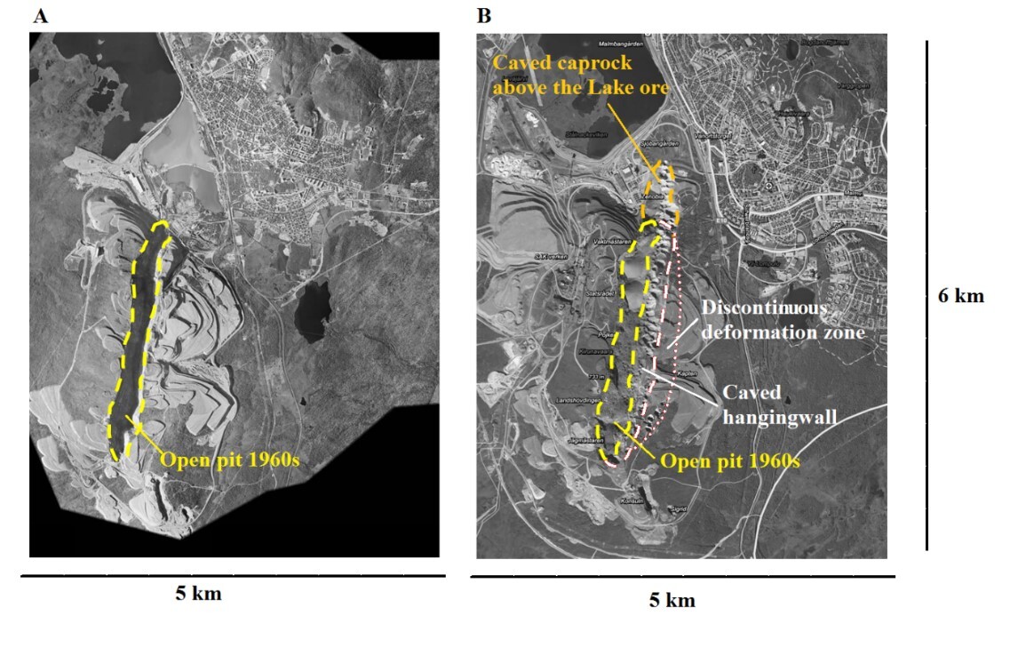
As mining progresses, the footwall contact becomes de-stressed and assumes a slope-like geometry. The footwall “slope” is partially supported by the caved rock masses from the hangingwall (Villegas & Nordlund, 2008). Despite this, damage on the footwall crest of the open pit and within the footwall rock mass at the Kiirunavaara Mine has been observed since the late 1980s.
To study the infrastructure damage in the footwall underground, a numerical study was initiated. The aim was to explain the origin of the infrastructure damage mapped in the footwall, understand the damage development in the footwall, and ultimately predict the extent of the future damage. It was decided to perform the study using PFC2D (Itasca, 2015) to allow brittle rock mass damage and the back-pressure from the hangingwall cave-material to be directly simulated.
Model Description
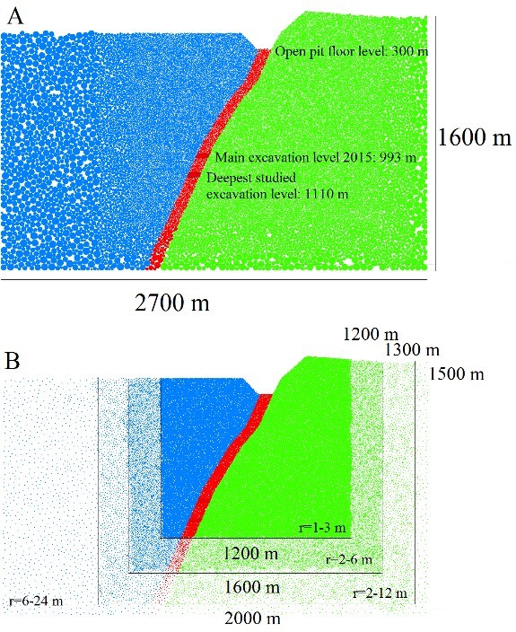
A model of a 2D mine section was built using PFC2D by creating a box 2700 m wide and 2000 m high. The box was filled with disc-shaped particles with uniformly distributed radii between 6 and 24 m to a porosity of 0.15 to ensure initial tight packing and adequate filling of the “construction box.” A smaller box was then cut from the filled volume and refilled with smaller radii particles to a porosity of 0.2. This step was repeated three times with the innermost box being 1200 m wide and 1500 m high, containing particles of radii between 1 and 3 m.
The particles were allowed to settle under gravity, then the simplified ground surface of the section was defined from CAD drawings and particles above this surface were deleted. The model was again solved to equilibrium under gravitational loading and any particles rebounding above the ground surface were automatically deleted.
Rock Mass Strength Calibration
To calibrate the rock mass properties, a calibration volume was defined as a rectangle 100 m wide and 200 m high. This volume corresponds to the volume of interest for analysis based on the distance between mappable infrastructure levels at the mine.
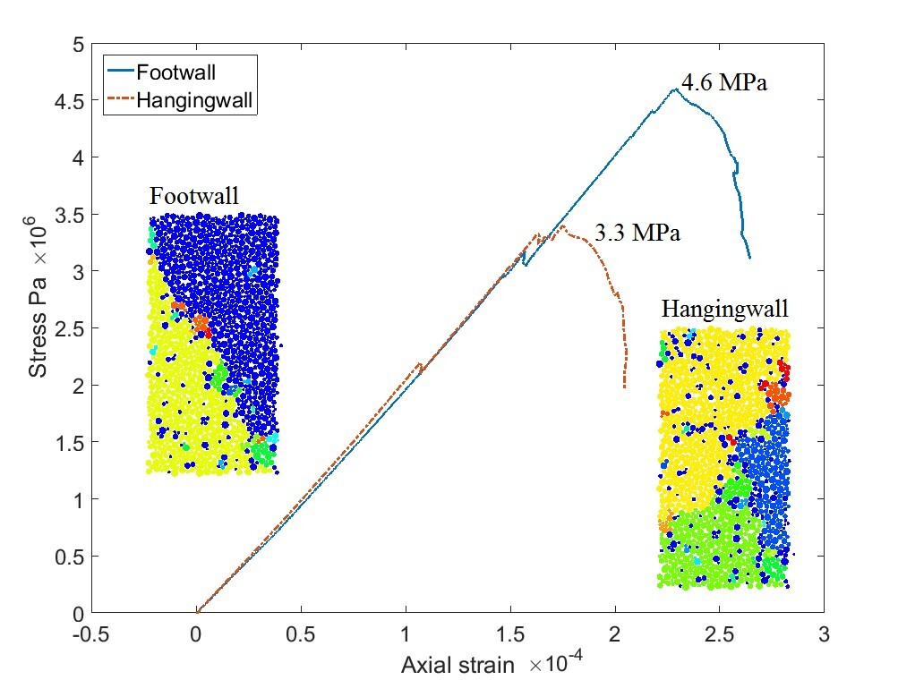
A numerical “rock core” was cut from the footwall at a depth of 700 m and close to the ore-contact with dimensions 240 m high and 100 m wide. The uppermost and lowermost 20 m were regrouped as pressure plates resulting in a final “test core” with dimensions 100 m by 200 m. The pressure plates were added to ensure a more uniform loading of the sample by a "perfect fit" of the pressure plates to the undulation surface of the specimen, resulting in the disc-shaped particles making up the rock mass matrix.
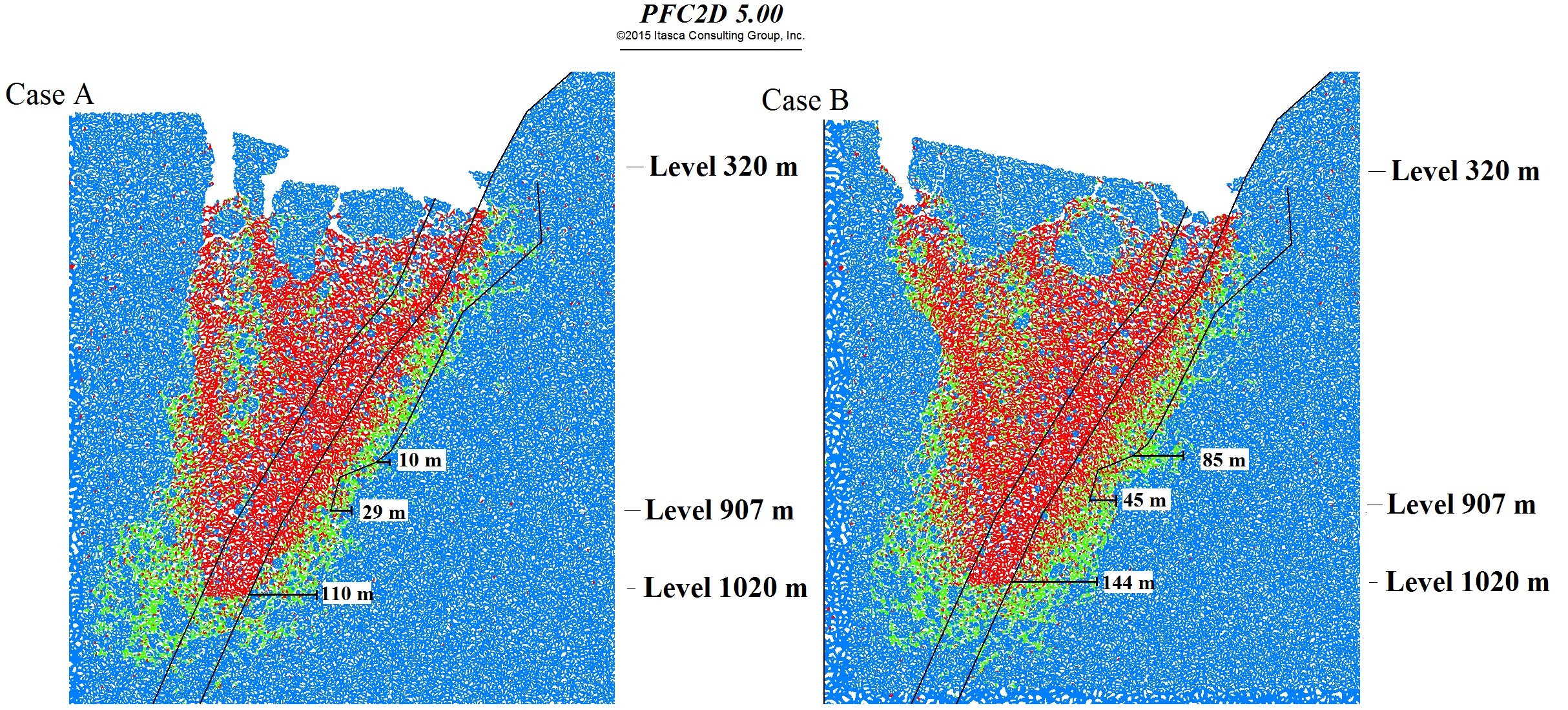
To study the influence of the cave material on the footwall stability, the hangingwall strength was lowered by 30% compared to the estimated in-situ strength in one model setup. Two models (strong vs. weak hangingwall) were then compared in relation to footwall damage development.
Results
It is clear that when the hangingwall is allowed to cave more readily, a wider cave zone is produced, which in turn leads to a larger extent of damage in the footwall rock mass.
This case study highlighted the importance of accurately determining the primary failure mechanisms when describing damage evolution.
For the Kiirunavaara Mine, significant calibration efforts have been made in the past to “forcibly” fit circular shear failure paths to the observed damage locations (e.g., Henry & Dahnér-Lindqvist, 2000) with the drawback of only fitting current observations and not being able to simulate the full evolution.
During the course of the PFC2D modeling campaign, it was concluded that the “standard” evaluation criteria for slope damage (i.e., shear band formation) did not describe the damage development well when considering the full life of the mine. The observable infrastructure damage in the footwall was not connected to any concurrent large-scale slope failure mechanism. Instead, the damage was proposed to be the result of “small” scale rock mass damages being mobilized due to decreasing confinement as mining progressed to deeper levels.
Summary
The numerical study showed that there is a clear relationship between the strength of the hangingwall and the damage developing in the footwall rock mass.
- A wider cave zone resulting from a relatively weaker model of the hangingwall produces deeper seated damages in the footwall than a narrower cave zone.
- The footwall and hangingwall cannot be studied separately if the full behavior of the footwall is to be simulated. The caving progression in the hangingwall is shown to significantly impact the width and flow behavior in the caved zone and, thus, the back pressure on the footwall.
- The damage in the footwall underground infrastructure is shown to be the symptom of local rock mass damage rather than the expected result, i.e., a coherent large-scale footwall failure.
References
Henry, E., and C. Dahner-Lindkvist. (2000) “Footwall stability at the LKAB's Kiruna sublevel caving operation, Sweden,” Massmin 2000: Proceedings of the 3rd International Conference and Exhibition on Mass Mining, pp. 527-532. Brisbane, Queensland, Australia: The Australasian institute of mining and metallurgy.
Itasca Consulting Group Inc. (2015) PFC — Particle Flow Code, Ver. 5.0. Minneapolis: Itasca.
Svartsjaern, M., and D. Saiang. (2017) “Discrete element modelling of footwall rock mass damage induced by sub-level caving at the Kiirunavaara mine,” Minerals, 7(7), 20, DOI:10.3390/min7070109.
Villegas, T., and E. Nordlund. (2008) “Numerical simulation of the hangingwall subsidence using PFC2D,” Massmin 2008: Proceedings of the 5th International Conference and Exhibition on Mass Mining, pp. 907-916. Luleå: Luleå University of Technology.