Mesa Verde Arch Analysis
Mesa Verde National Park, located in southwestern Colorado, is the site of Spruce Tree House, which is the third largest and best-preserved cliff dwelling in the Park. The nose of the alcove contains a thin arch delineated by a persistent curved crack, which extends about 270 ft north from above the south end of the alcove. Recently, rockfalls from the arch and adjacent rock surfaces demonstrated the need for a new assessment of arch stability and stabilization. Itasca was retained by the National Park Service (NPS) to investigate the arch, conduct a stability assessment, conduct 3D modeling, identify remediation options, recommend the preferred option, and estimate construction costs.
Project Background
The Spruce Tree House cliff dwelling was constructed about 800 years ago, in a naturally-formed alcove about 216 ft wide by 89 ft deep. The alcove is located across a deep, narrow canyon from the Park museum, and is a very popular destination. The nose of the alcove contains a thin arch delineated by a persistent curved crack, which extends about 270 ft north from above the south end of the alcove. The crack is up to several feet wide, and the arch cross section is roughly 10 ft thick by 20 ft high. A 1960s investigation led to a stabilization program that included rockbolts and a thorough cleaning and grouting of the crack. Recently, rockfalls from the arch and adjacent rock surfaces demonstrated the need for a new assessment of arch stability and stabilization.
Model Description
The sandstone cliff at the Spruce Tree House Alcove is composed of tan, fine to medium grained sandstone with intermittent layers of shale. The layers of shale have eroded in some areas and have created slight to moderate overhangs in the sandstone. This project focuses on the arch that was stabilized in the 1960s (hereon referred to as the local arch) and the Richardson crack, originally mapped by William Richardson, that runs parallel to the outer edge of the alcove (hereon referred to as the Richardson crack).
Model
In the 1940s, William Richardson mapped and measured the location of the Richardson crack at Spruce Tree House (Richardson, 1940). NPS provided these plans and cross-sections to Itasca to assist in determining the site geometry. Additionally, NPS provided 3D scans of the arch which were used to create the geometry. Drilling, surveying, crack monitoring, turtle back characterization, and joint characterization was conducted during a site investigation performed by Itasca in 2017 above the Spruce Tree House alcove. Joint information and arch geometry information collected on site was used to create the model geometry. Lab testing was performed on the sandstone and was used to determine rock mass properties.
3DEC Model Results
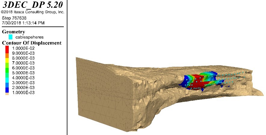
A 3DEC model was developed based on the geometry from the LIDAR survey, including assumptions about the geometry of the crack that defines the arch. The portion of the Richardson crack that was remediated in the 1960s is believed to have frictional properties but no cohesion. The Richardson crack was extrapolated north and south of the remediated segment. The extrapolated segment is believed to have both cohesion and friction. The model was calibrated, meaning sandstone strength properties were adjusted, so that the arch was just stable with the existing 1960s rockbolts discounted.
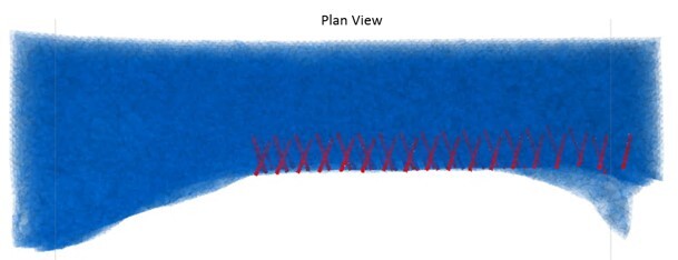
Three rockbolt configurations were modeled, reticulated and unreticulated patterns with 79 25-ft long rockbolts installed in three rows, and a reticulated pattern with 58 18-ft long rockbolts in three rows. The recommended rockbolt type is a Williams R1H high grade, hollow-core, pretensioned rockbolt with a yield load of 100,000 lbs, tensioned to 38,000 lbs.
Several parameters were used to determine the stability of the model. First, velocity histories were recorded at multiple locations in the model. If the model is in equilibrium, the velocity histories will converge to a near-zero value. Additionally, the failure state of the model zones of the local arch were analyzed to determine if the model was stable.
The entire model appears to be stable up to a factor of safety of 2.0. The velocities at the six recorded locations all converge to near-zero, with the rock below the shale layers exhibiting the most movement and the zones exhibiting failure is limited. Once the SRF is increased to 3.0, the rock below the shale seams does not appear to converge, but the section of the arch above the shale seams converges. Observing the failure state of the zones in the model, the failure is much more extensive at an SRF of 3.0 than at 2.0, including an increase in shearing in the southern pillar and tension in the northern pillar.
Summary
- The entire model appears to be stable up to a factor of safety of 2.0.
- The reticulated pattern more effectively stabilizes the arch by stitching the rock together.
- The analysis also showed, based on predicted rock bolt axial forces from the 25-ft long option, that shorter rock bolts would be adequate.
- The 3DEC model also predicted that the recommended remediation would not stabilize blocks on the underside of the arch.
References
Richardson. (1940, June 29) “Study of Cracked Rock Formations over Spruce Tree House.”